For the Introduction to VLSI course at Texas State University, students are expected to be able to design an 8-bit Full Adder using CMOS transistors, size each transistor according to delay optimization or the pull up/down strength of each gate, and draw the design out in LTSpice and Microwind. I worked in a 3 person team to complete the implementation of an 8-bit Carry-Select adder where I took care of the gate-level design and the Microwind implementation while my teammates took care of the LTSpice implementation.
CMOS Implementation
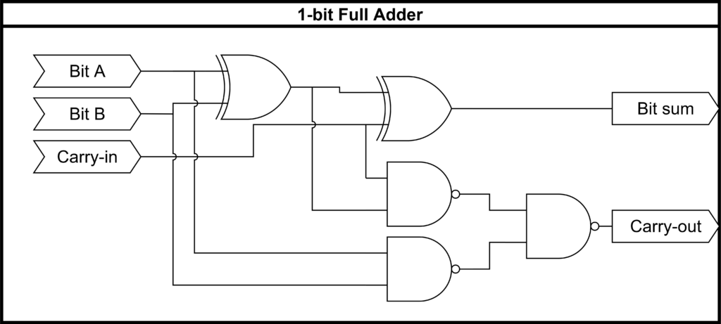
The gate-level design of the 8-bit adder uses only CMOS inverters, 2-bit XOR gates, and 2-bit NAND gates. The CMOS design was chosen for the ease of design and implementation as well as the low power requirements.
Adder Design
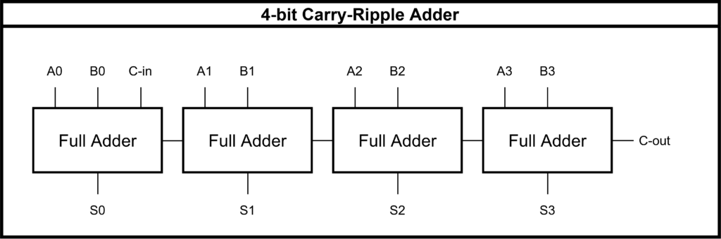
A pure Carry-Ripple design is the simplest and smallest Full Adder design, but it is also the slowest. The 8-bit Carry-Select design was chosen as it achieves a better balance of speed and complexity that seemed ideal to practice with.
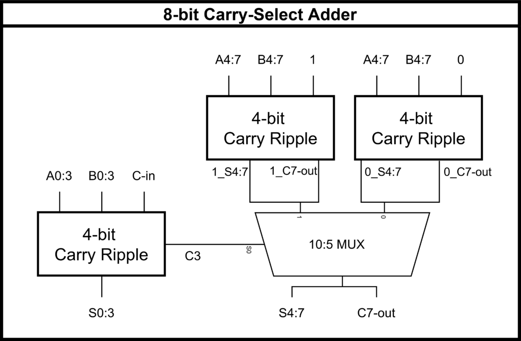
The Carry-Select design works by starting with three 4-bit Carry-Ripple adders. The first adds bits 0-3, the second adds bits 4-7 assuming the bit-3 carry-out will be 1, and the third adds bits 4-7 assuming the bit-3 carry-out will be 0. The bit-3 carry-out is then used as the input select for a 10:5 MUX that decides whether the second or third Carry-Ripple adder will be used to output bits 4-7 and the final carry-out.
Microwind Implementation

The standardized cell design features shared rails for ground and voltage supply, a standard polysilicon length of 100nm, and a standard cell height of 5000nm. Each gate was designed with pull up/down strength equivalent to an Inverter with a PMOS width of 600nm and an NMOS width of 300nm. The design passes Microwind’s built-in design rule check and successfully performs 8-bit addition.
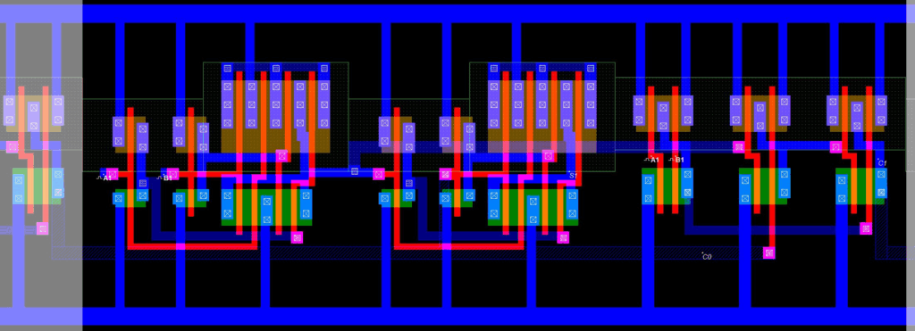
The 1-bit full adder implementation features the two 2-bit XORs followed by three 2-bit NANDs. Highlighted in white is the end of the previous cell providing the carry-in.
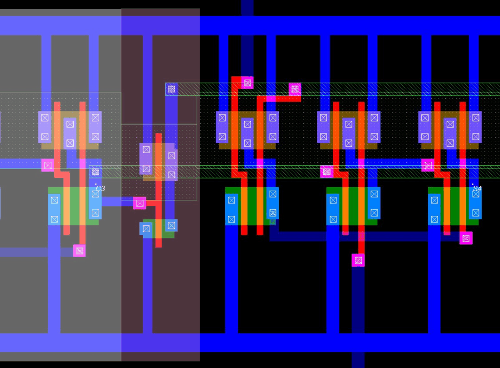
After the end of the first 4-bit Carry Select (highlighted in white), the bit-3 carry out is run through an inverter (highlighted in red) and used to create two rails of Metal 4 that supply the select to each cell of the 10:5 MUX (cell 1, bit-4 output, shown here).
However, the design can still be further optimized.
- For industry practices, it has been advised to alternate the metal layers such that each layer is orthogonal to its neighbors. This was not done here due to the basic nature of the design, but this could be implemented.
- Simply stacking the standard cells designed earlier in the course caused empty space to build up. The standardized 5000nm cell height and the horizontal gap between neighboring cells can both be reduced.
- It is possible to create a vertically mirrored design of the 4-bit Carry-Ripple and then stack the adders with shared rails. Making the full unit have a a square design with fewer rails would be preferable to easily fit many of the unit on a chip.